An Integrated Building System for Spain
ISB® brings wall and floor elements together through architecture, engineering and project-specific system planning — creating one coordinated approach from design to construction.
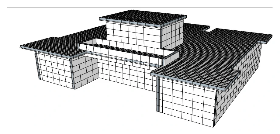
The building is the system.
Not the individual element.
ISB® is conceived as a coordinated building system in which wall elements, floor elements and structural reinforcement are developed together within the engineering of each project. The result is not a catalogue of isolated components, but a structural approach connecting architecture, system planning and construction.
Wall System
ISB-PHC-250 wall elements form part of the project-specific wall structure and are coordinated with reinforcement, junctions and the wider structural design.
Floor System
Dedicated ISB-PHC-250 floor elements extend the system beyond the walls, allowing horizontal and vertical building components to be considered as part of one structural concept.
Structural Coordination
Reinforcement and junction logic connect the individual elements. Their configuration is developed through engineering for the requirements of the specific building project.
Individual components become valuable when they work together.
The ISB® approach coordinates walls, floors, reinforcement and junctions within a single project workflow. Architecture defines the building. Engineering develops the structural solution. ISB® system planning translates that solution into coordinated building elements and connections.
System configuration, reinforcement and connection details are determined through project-specific engineering and the applicable technical requirements.
Engineering-led design
Two structural elements.
One coordinated system.
The ISB® system combines dedicated wall and floor elements within the same project logic. Each component has its own structural role, while engineering, reinforcement and connection design bring them together as part of one coordinated building structure.
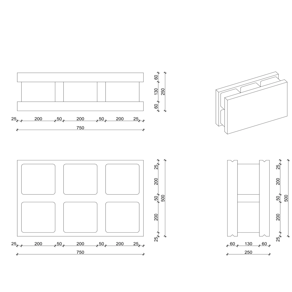
ISB-PHC-250 Wall Element
The wall element forms the vertical part of the ISB® structural concept. Its use is coordinated with reinforcement, wall junctions, openings and other project-specific structural details rather than being treated as an isolated building product.
- Part of the integrated wall and floor system
- Coordinated with vertical and horizontal reinforcement
- Adapted to the architecture and structural design
- Junctions developed within project-specific engineering
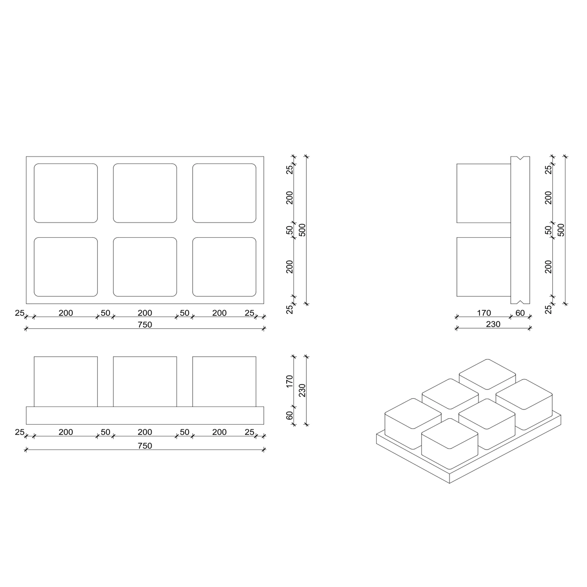
ISB-PHC-250 Floor Element
The dedicated floor element extends the ISB® system into the horizontal structure. It is integrated with the surrounding wall system through reinforcement and connection details developed for the individual project.
- Dedicated horizontal system component
- Designed to work together with the wall structure
- Coordinated with floor reinforcement and junction design
- Integrated into the overall structural engineering concept
The connection between wall and floor is where the system becomes structural.
Walls and floors are not planned independently. Their interfaces, reinforcement and junctions are coordinated through engineering so that vertical and horizontal elements form part of one continuous structural concept.
Element configuration, reinforcement and connection details depend on the architecture, structural design and technical requirements of the individual project.
Wall + Floor Integration
From elements to a coordinated structure.
The wall and floor elements become part of a building system through structural engineering, reinforcement and carefully coordinated interfaces. Integration is developed at project level — where architecture, loads, geometry and construction details come together.
Structural continuity is designed through the connections between components.
A building is more than a collection of wall and floor elements. Their relationship must be engineered as a whole. Within the ISB® system, reinforcement, wall intersections, floor interfaces, openings and base conditions form part of the same coordinated structural logic.
Vertical Structure
Wall elements, reinforcement and wall junctions are coordinated within the structural concept of the project.
Horizontal Structure
Floor elements and their reinforcement are developed together with the surrounding vertical structure.
Junction Logic
Corners, intersections, wall-to-floor interfaces and openings require coordinated connection details.
Project Engineering
Structural configuration is determined for the geometry, loads, site conditions and technical requirements of each building.
Architecture
Building form, layout, openings and spatial requirements define the architectural starting point.
Engineering
Structural requirements, actions and project conditions are translated into the engineering concept.
System Planning
Elements, reinforcement and interfaces are coordinated within the ISB® building system.
Integrated Structure
The coordinated components form the structural basis for the building and its construction process.
The system becomes visible in the details.
Wall corners, intersections, floor connections, openings and base conditions show how individual elements are coordinated at the points where structural systems meet.
Connections define the system.
Wall and floor elements become part of one coordinated building structure through the points where they meet. Corners, intersections, floor interfaces, openings and base conditions are therefore not secondary details — they form part of the structural logic of the ISB® system.
The system continues through every structural interface.
Connection geometry, reinforcement and detailing are coordinated through engineering for the individual building. The examples below illustrate key junction principles within the documented ISB® system.
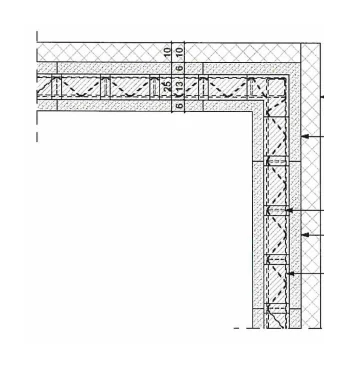
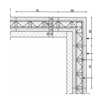
External Wall Corner
At an external corner, adjoining wall elements and their structural reinforcement must remain part of the same coordinated wall system. The corner detail demonstrates how the system geometry continues through a change in wall direction.
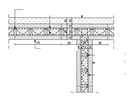
Internal Wall Corner
Internal corners require the same structural coordination as the external envelope. Element geometry and reinforcement are developed so that intersecting walls remain connected within the overall structural concept.
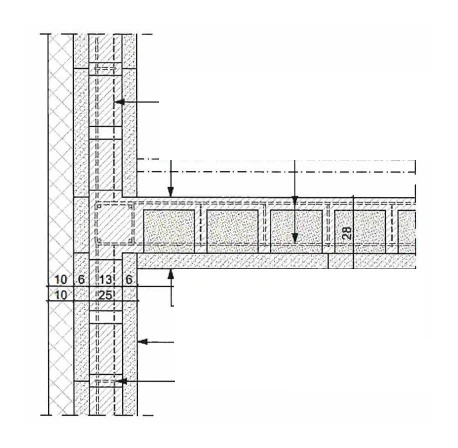
Main Wall Junction
Where one structural wall meets another, the intersection becomes part of the system planning. The connection coordinates the geometry of both wall directions together with the required reinforcement arrangement.
Wall-to-Floor Connection
The intermediate floor junction is one of the clearest examples of the integrated system concept. Vertical wall elements and horizontal floor elements are coordinated at the interface through structural detailing and reinforcement.
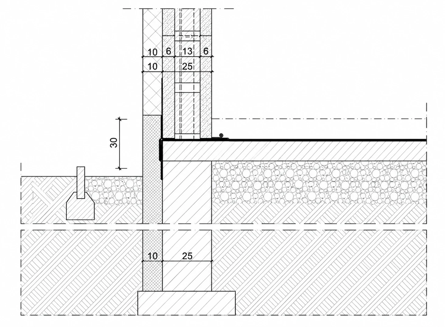
Base Connection
At the base of the building, the wall system must connect with the foundation, floor build-up and surrounding construction. This interface brings structural, envelope and moisture-related detailing together within one project condition.
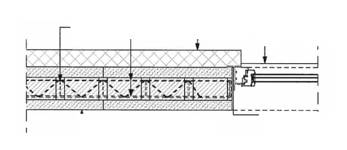
Window Opening
Openings interrupt the continuity of the wall and therefore require coordinated detailing around the window perimeter. Head, sill and side connections are developed as part of the wall and envelope specification rather than as isolated construction details.
Standardised logic does not mean identical detailing.
These drawings illustrate documented system principles. Final connection geometry, reinforcement, dimensions and adjacent construction layers are determined through the engineering and specification of the individual project.
The connection details explain how components meet. The next step is to examine how the complete building system addresses thermal, acoustic, fire, structural and moisture-related performance requirements.
Performance begins with design.
A building system must do more than create structure. Thermal behaviour, acoustic comfort, fire performance, structural actions and moisture management all influence how the complete building performs within its climate, location and use.
Structure, envelope and building physics must be considered together.
ISB® provides a coordinated wall and floor system around which project-specific technical performance can be developed through engineering, specification and the complete building design.
Thermal Performance
Thermal performance is determined by the complete building envelope, not by one structural component alone. Wall and floor assemblies, insulation layers, junctions and project-specific detailing are coordinated to meet the thermal requirements of the individual building.
Envelope · Insulation · JunctionsAcoustic Comfort
Acoustic behaviour depends on the complete assembly and the way building elements connect. Wall and floor specifications can therefore address airborne sound, impact noise and junction conditions as part of the overall acoustic design of the project.
Airborne Sound · Impact Noise · InterfacesFire-Performance Design
Fire performance is addressed through the structural concept, material specification, wall and floor assemblies and the requirements of the individual project. The system provides a basis for coordinated fire-performance engineering rather than a generic performance claim.
Materials · Assemblies · Project RequirementsStructural Performance
The reinforced structural concept allows loads and project-specific actions to be considered through engineering. Building geometry, spans, wall positions, openings, connections and site conditions all contribute to the final structural design, including relevant seismic and wind actions where required.
Loads · Geometry · Seismic + Wind ActionsMoisture Management
Building-envelope design must manage heat and moisture together. Layer build-ups, junctions, waterproofing, vapour behaviour and local exposure conditions are considered as part of the complete project specification.
Waterproofing · Vapour Behaviour · Layer Build-UpTechnical performance is engineered, not assumed.
Performance requirements depend on the building, location, intended use, architecture and applicable technical standards. Final values, assemblies and specifications are therefore defined during project-specific engineering and documentation.
Performance defines how the system responds to technical requirements. The next step is to look at the types of projects in which this coordinated wall and floor system can be applied.
One system. Different project types.
ISB® is not linked to one predefined house type or one architectural expression. The coordinated wall and floor system can be considered for different building and development scenarios, provided the structure is engineered for the requirements of the individual project.
Start with the project — then develop the system around it.
Site, architecture, intended use, scale and structural requirements define the starting point. ISB® planning then coordinates the wall, floor, reinforcement and connection logic around the actual building.
New Homes
Detached houses, villas and other residential projects can be developed around the ISB® system while maintaining project-specific architecture, spatial organisation and structural design.
Villas · Houses · Residential ProjectsExtensions
Where the existing structure and project conditions allow, the system can be considered for extensions that add new internal space while connecting new structural elements to an existing building.
Side Extensions · New Volumes · Building AdditionsAdditional Floors
Selected projects may allow additional levels to be considered above an existing structure. Suitability depends on the existing building, structural verification, project loads and the engineering solution developed for the new construction.
Additional Levels · Structural Assessment · Project EngineeringResidential Developments
For projects involving multiple buildings or repeated building types, a coordinated system approach can help connect architecture, engineering, element planning, production and construction within a repeatable project workflow.
Repeated Typologies · Coordinated Planning · Development ProjectsRedevelopment Projects
Certain redevelopment scenarios may benefit from a system-based structural solution where new construction must be coordinated with an existing site, building condition or revised architectural programme.
Site Adaptation · New Structure · Existing ContextArchitect-Led Projects
ISB® can be introduced into projects already being developed by architects, engineers, developers or contractors. The system planning process integrates with the professional project rather than replacing it with a predefined building model.
Architects · Engineers · Developers · ContractorsDifferent buildings. The same coordinated project logic.
The application changes, but the principle remains consistent: architecture defines the project, engineering defines the structural requirements, and ISB® system planning coordinates the elements, reinforcement and connections around that solution.
Different project types can use the same coordinated system logic. From here, the next step is to connect the building system with a real site, architectural concept and project brief.