
ISB® Building System

Technical Performance

Technical performance begins with engineering.

The ISB® Building System is supported by documented wall and floor elements, reinforcement principles and structural connection details. Final performance is developed through project-specific engineering, specification and building design.
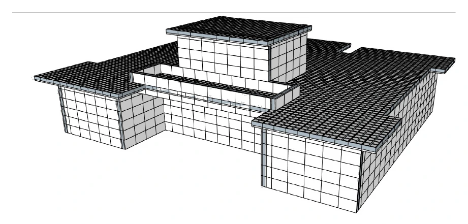
01 Documented System
02 Project-Specific Engineering
03 Technical Coordination
Integrated ISB® wall and floor structure illustrating the technical building system
Wall + Floor + Reinforcement + Connection Logic
Documented System

Engineering starts from documented system logic.

The technical basis of ISB® is not a collection of isolated building products. The system brings together wall elements, floor elements, reinforcement and connection principles within a coordinated structural concept.

Technical Documentation
National Technical Assessment A-49/2025
ISB® system documentation
ISB-PHC-250 wall and floor elements

From system documentation to project-specific design.

The technical documentation provides the reference framework for the ISB® system and its principal components and connection logic. For an individual building, this system basis is combined with the architecture, structural calculations, site conditions and applicable project requirements.

This distinction is important: documented system principles provide the technical foundation, while the final building solution is developed through project-specific engineering.

01

Wall Elements

Documented wall-element geometry provides the basis for vertical structural planning within the system.

02

Floor Elements

Horizontal floor elements form the second principal component of the coordinated wall-and-floor structural concept.

03

Reinforcement

Reinforcement principles support the structural design of wall and floor elements according to the requirements of the project.

04

Connections

Corners, wall intersections, floor interfaces, bases and openings form part of the documented connection logic of the system.

Technical Principle

Documentation defines the system. Engineering defines the building.

Dimensions, reinforcement, structural actions, connection details, envelope build-ups and final performance requirements must be determined for the individual project. The documented system provides the technical framework within which that engineering takes place.

The documentation establishes the system framework. The next step is to examine how wall elements, floor elements and reinforcement work together as a structural system.

Next: Structural System
Structural System

Wall, floor and reinforcement work as one system.

The structural concept is built around three coordinated parts: vertical wall elements, horizontal floor elements and reinforcement. Their geometry and connections are developed together within the engineering of the individual building.
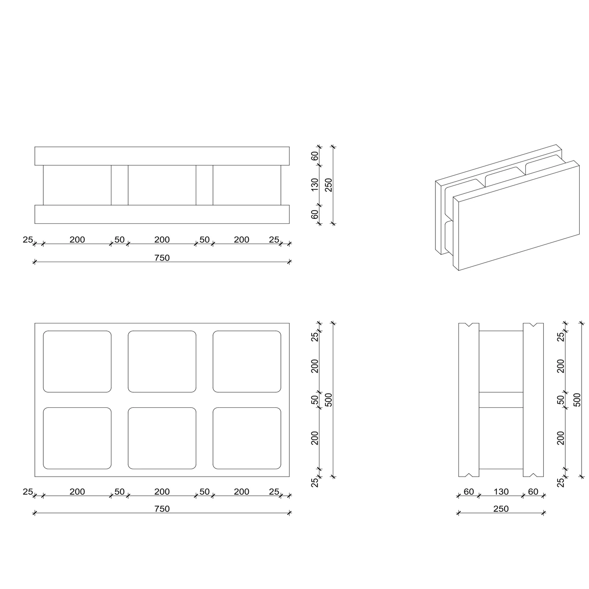
Technical drawing of an ISB® wall element with dimensions and sectional views
01 Vertical Structure

ISB-PHC-250 Wall Element

The wall element provides the vertical system geometry around which reinforcement, openings, intersections and project-specific structural detailing can be coordinated.
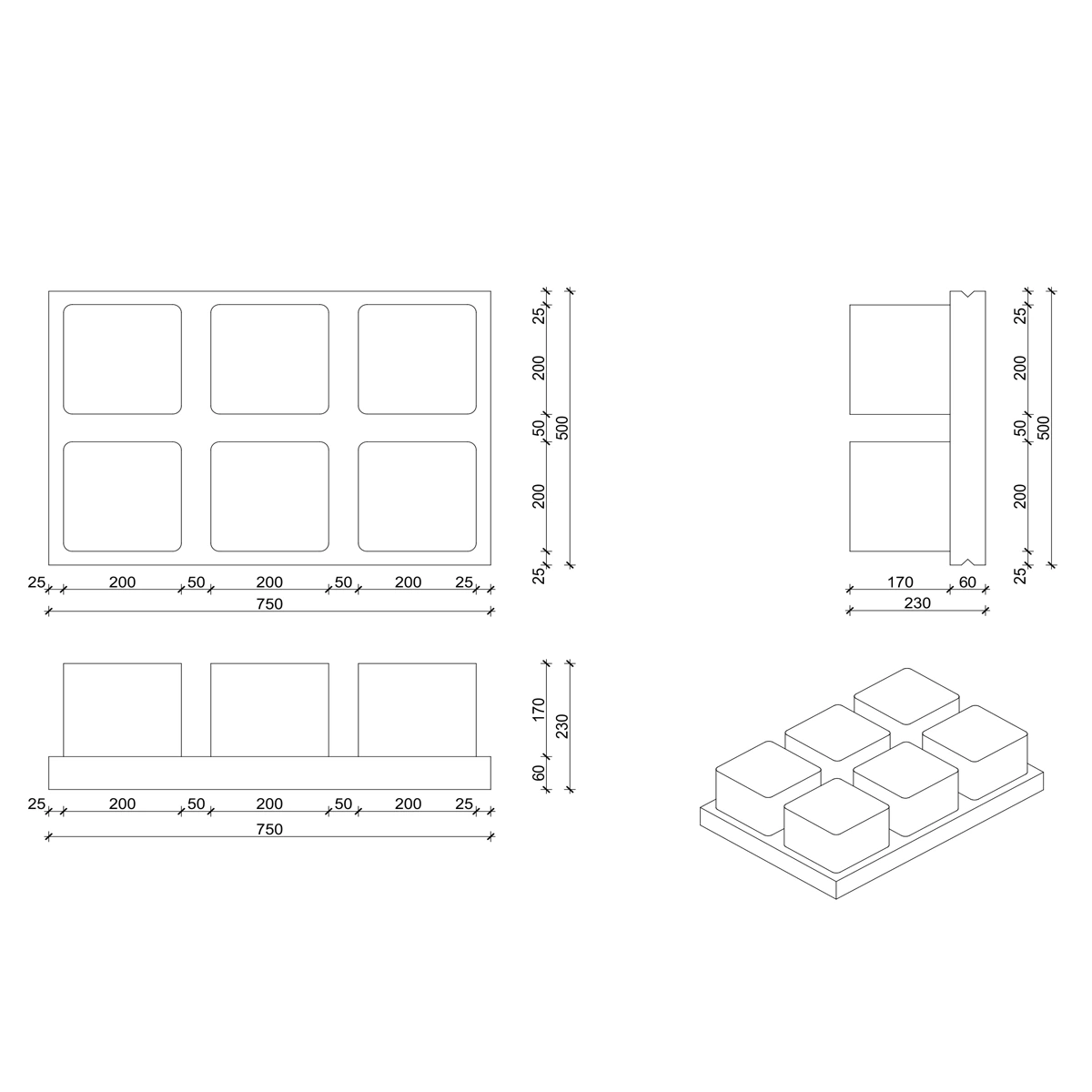
Wall Geometry · Openings · Junctions
Technical drawing of the ISB® PHC-250 floor element with dimensional and sectional views
02 Horizontal Structure

ISB-PHC-250 Floor Element

The floor element extends the same system logic horizontally and is coordinated with the surrounding walls, structural interfaces and reinforcement design.
Floor Geometry · Spans · Wall Interfaces
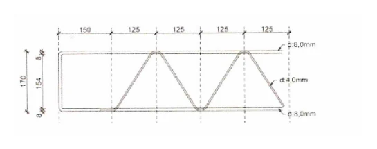
ISB® floor reinforcement detail showing reinforcement geometry, spacing and dimensions
03 Structural Reinforcement

Reinforcement Logic

Reinforcement connects the system geometry with the structural engineering of the project. Wall and floor reinforcement are specified according to the building configuration and calculated structural requirements.

Walls · Floors · Project Engineering
Structural Integration

The technical value lies in how the components connect.

Wall and floor elements are not designed as unrelated products. Reinforcement and connection details link vertical and horizontal components within one coordinated structural concept developed for the specific building.

The structural system establishes how the building is formed. The next step is to examine how the complete assembly addresses the technical performance requirements of the project.

Next: Building Performance
Building Performance

Performance belongs to the complete building.

Structural components alone do not define how a building performs. Envelope design, assemblies, connections, materials and project conditions must be considered together when technical requirements are developed for a specific building.

01

Thermal

Thermal performance is developed through the complete envelope, including wall and floor assemblies, insulation layers, junctions and project-specific construction details.

02

Acoustic

Acoustic design depends on complete assemblies and interfaces. Airborne and impact sound considerations can therefore be addressed as part of the overall building specification.

03

Fire

Fire performance must be considered through materials, structural design, wall and floor assemblies and the technical requirements applicable to the individual project.

04

Structural

Loads, spans, openings, connections, geometry and relevant seismic or wind actions are addressed within the structural engineering of the building.

05

Moisture

Waterproofing, vapour behaviour, layer compatibility and exposure conditions form part of the complete envelope and junction design.

Performance Principle

Technical values must follow the project specification.

Final thermal, acoustic, fire, structural and moisture-related performance depends on the complete building configuration, specification and applicable technical requirements. Values should therefore be confirmed through the engineering and documentation of the actual project rather than assumed from generic system claims.

Building performance explains what the complete design must address. The next section shows a selection of the technical details used to coordinate the system at critical structural interfaces.

Next: Technical Details
Technical Details

The system becomes visible at the connections.

The structural logic of ISB® is expressed most clearly where components meet. Corners, wall intersections, floor interfaces and base conditions show how the building system is coordinated beyond the individual element.
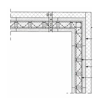
ISB® external wall corner connection detail showing the wall system junction
01 Corner Connection

External Wall Corner

The corner detail demonstrates how adjoining wall elements and their structural logic continue through a change in building direction.
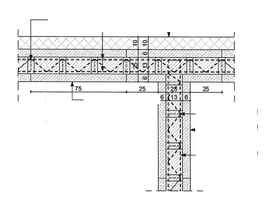
ISB® main wall junction detail showing the structural connection between intersecting wall elements
02 Wall Intersection

Main Wall Junction

Intersecting structural walls require coordinated geometry and reinforcement so that both directions remain part of the same structural concept.
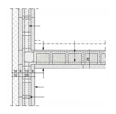
ISB® intermediate floor connection detail showing the structural junction between wall and floor elements
03 Wall + Floor Interface

Intermediate Floor Connection

The wall-to-floor interface links vertical and horizontal structural elements through coordinated reinforcement and connection detailing.
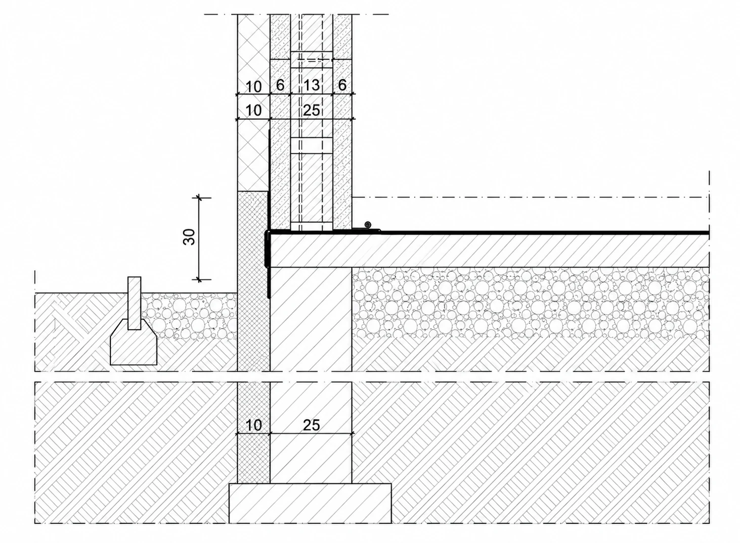
ISB® base connection detail showing the structural junction between the wall, floor and foundation
04 Foundation Interface

Base Connection

At the base of the building, the structural wall system connects with the foundation, floor construction and surrounding envelope conditions.

Detail Principle

Reference details provide the logic. The project defines the final solution.

These drawings illustrate documented ISB® connection principles. Final dimensions, reinforcement, adjacent construction layers and connection geometry are defined through the engineering and specification of the actual building.

The documented system provides a technical framework. Turning that framework into a real building requires architecture, structural design, project-specific engineering and coordinated construction planning.

Next: From Documentation to Project
From Documentation to Project

Technical documentation is the starting point.

A documented system becomes a real building only when it is connected with architecture, structural calculations, local conditions, project requirements and coordinated execution.

ISB® Building System · Spain

Documented system. Project-specific engineering.

Architecture · Engineering
System Planning · Construction